REAR SUSPENSION MODS
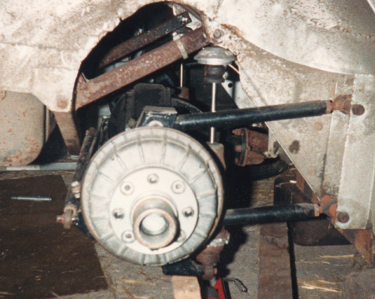
5 link back axle well 6 if you're counting

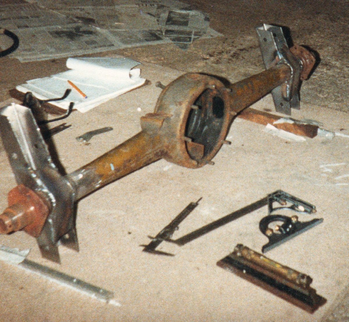
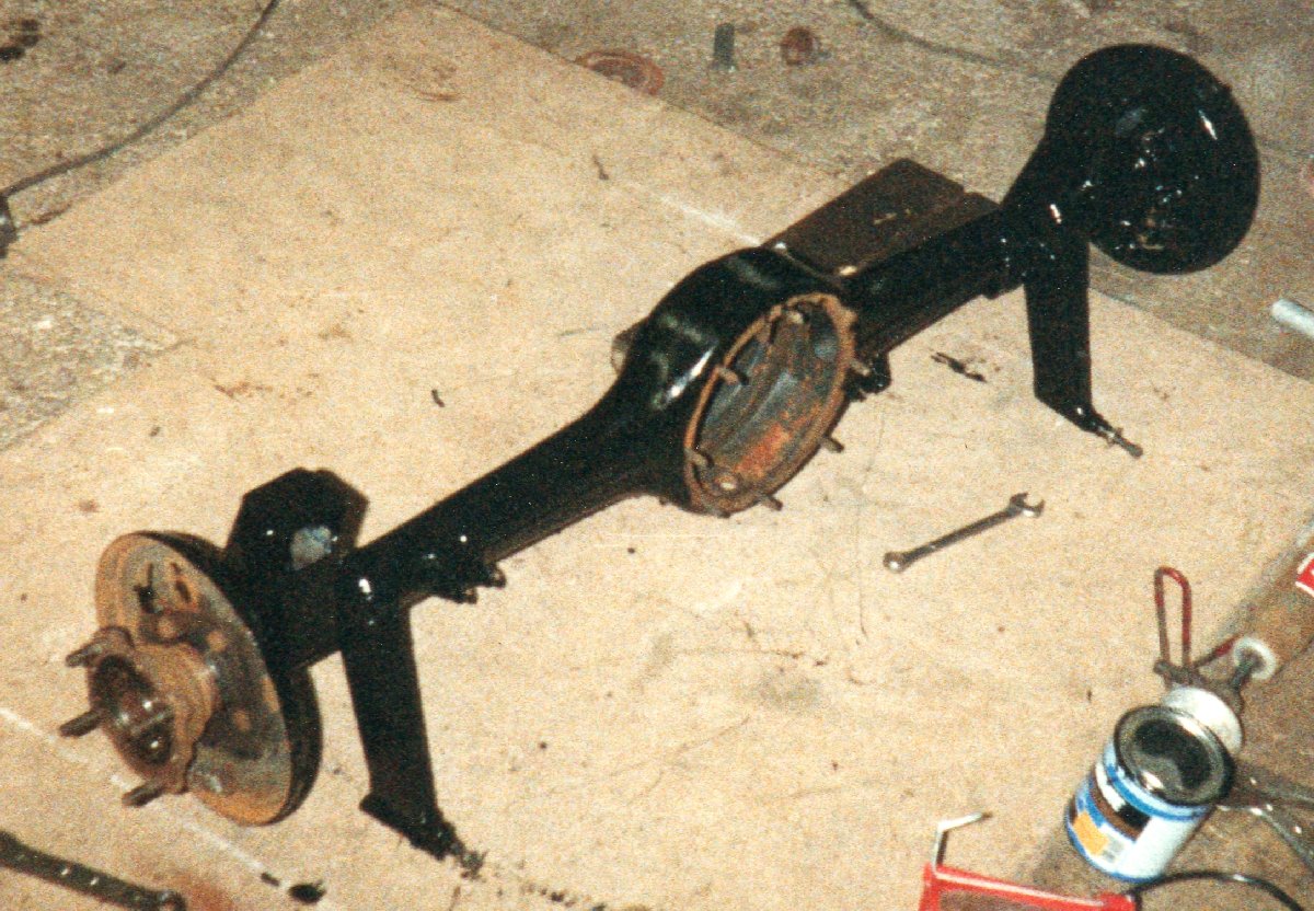
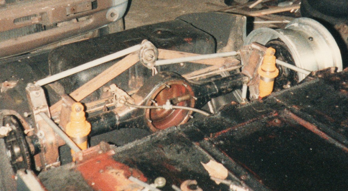
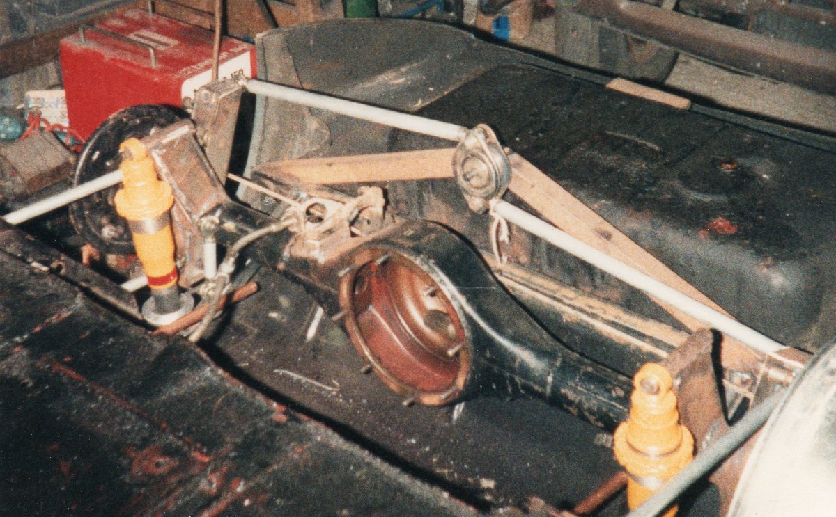
This one was design by Chris Norris and I lofted (developed) and made the brackets and jigs

This replaced the links and quarter eliptic on a frog with 4 rose jointed rods and adpatation of a watts linkage, normal with a watts linkage the swivel would but mounted on the axle casing and the rod ends fixed to the chassis. A panhard rod could have been used but with that the axle would move sideways and the geometry would always be changing.


Click to Enlarge
This shows the basic axle, this was from a semi-eliptic wire wheeled sprite but a second one was made using an Anglia 105E axle casing. By this stage all the original suspension mounts had been cut and then ground off and the new uprights were set up and welded. Set up and mearsure at least twice before welding. The towers were made as thin as possible and then doubled where bolts went through and boxed. 
In this shot you can see it now has the mounts for the coil over shocks and brackets to take rod ends for a rear anti-roll bar.
Click to Enlarge
Click to Enlarge
 Here the axle is in for a test fitting, the "A" frame supporting the pivot for the swivel has been mounted. This is the stage where you can move the axle about and check everything moves freely and there is no foulling anywhere. 
 This lets you see our planned rear anti-roll bar. If your fitting a rear bar remember you'll probably need to increase the front bar rate. On the 105E axled one a channel cross member was fitted with a series of holes so the coil over shock could be inclined to change spring rates without changing springs.
Click to Enlarge
Click to Enlarge
This is it all bolted in and having been used for a few years(spring removed). Note the center lock wheel hubs and rather than spline drive these had four pegs a bit like a normal wheel. This one used a channel fixed to the rear bulkhead to take the drag links. 
 

It was never needed or done on this one but I know if you haven't got everything lined up perfect then a lot of people take out one of the drag links to stop the axle locking in certain positions or fit rubber bushed instead of rose joints.

 
When working out link lenghts and pickup positions, remember there are many variations and everyone will cause a different effect when they move (model it in cardboard or on a PC). Also as one side is compressed and the other side lifts this will cause some amount of rear wheel steering. This can be made to work for you once your aware of what it's doing.


            MODS MENU