ALSO CHECK OUT BONNET COOLING MODS
BY-PASS HOSE
IF YOU BLOCK OFF THE BY-PASS HOSE USE LATE A-SERIES (ALLEGRO MK
II 1100/1300 74-80,METRO 80>) PUMP G_MWP207 Q_QCP3710 AS THE PUMP HAS THE
PUMP BY-PASS BLOCKED OFF ANDDON'T FORGET TO FIT A THERMOSTAT BLANKING SLEEVE.
CABLE OPERATED HEATER CONTROL VALVE - M_MHV100
ELECTRIC COOLING
FANS
Why? This frees up some horse power, gives better throttle response
(due to not having to spin up the fan), reduces noise, and can increase
fuel economy.
There are 3 ways of wiring these
1, switch on the dash, if you see the engine is getting too hot, sat
in traffic or coming to the end of your journey you switch it on. This
relies on you!
2, most common, a temperature sensitive switch is fitted to the rad
(these are sometimes adjustable) when the temp get to a pre-set temp it
switches on, when it cools it goes off. This can be wired direct to the
battery so it will cool after you walk away from the car after switching
it off.
3, a temperature sensitive switch is fitted to the rad, but it
also has an override switch so if you see a long queue ahead or long slow
hill you can turn it on and make sure you have a rad full of cool water
before you need it.
WARNING WHEN REMOVING STANDARD FAN REMEMBER
TO SHORTEN PULLEY BOLTS BEFORE REFITTING THEM OR YOUR WATER PUMP CAN JAM
ELECTRIC WATER PUMPS
WHY? THIS FREES UP SOME HORSE POWER AND STOPS THE RISK OF CAVITATION ON HIGH REVING ENGINES, YOU CAN ALSO RUN IT AFTER STOPPING THE ENGINE THUS ENSURING IT COOLS DOWN PROPERLY. AS NORMALLY WHEN YOU STOP THE TEMP GOES THRO THE ROOF.
THERE ARE A FEW AFTER MARKET ONE THAT WILL DO THE JOB. USED TOGETHER
WITH THE STANDARD PUMP WITHOUT THE BELT ON OR WITH PUMP BLANKING PLATE
WITH 18mm INLET PIPE. REMEMBER IF YOUR MAKING A BLANKING PLATE YOU
MIGHT WANT A DEFLECTOR PLATE ON THE BACK OF IT TO DIRECT THE WATER AS THE
PUMP WOULD. IF NOT YOU MAY FIND NO 1 CYLINDER GETS TOO HOT AS YOUR PUMPING
THE COOL WATER STRAIGHT TO THE BACK OF THE BLOCK, YOU WON'T GET THIS PROBLEM
IF YOU LEAVE THE OLD PUMP IN PLACE.
John Benson of Davis, Craig pty. ltd. kindly sent me this and it says
what I tried to say only better. Thanks John.
The Mechanical Water Pump is one of the last mechanical components
of the modern engine which has long been considered an inefficient component
that was designed as an accessory from the very first engines. A mechanical
belt driven pump installed on your cars engine runs at the same speed
as the engine regardless of engine temperature. Example: when travelling
at higher speeds, the engine require less cooling as ram air is naturally
cooling the engine however, the engine revs are high as a consequence the
mechanical water pump is providing excessive coolant whilst draining the
engine of power. Then in heavy traffic in high ambient temperatures, the
engine is only idling, low revs and so is the belt driven mechanical pump,
even though in this situation, extra coolant flow is required to cool the
engine.
With an Electric Water Pump and a EWP/Fan Digital Controller, the speed of the pump is managed commensurate with engine temperature. The Controller varies the voltage to the pump and therefore varies the coolant flow, hunting for the targeted (set) temperature. When the engine reaches the targeted temperature the Controller locks on, constantly varying the pump speed, maintaining the target temperature independent of the engine speed.
The important improvement for your vehicles engine is the increased power the mechanical pump steals from your engine is returned to the drivetrain and also decreases fuel consumption. By removing the parasitic power loss of belt-driven water pump, the EWP may provide up to 10kw of extra power and additional fuel savings. The engine power used by the mechanical pump increases as the cube of its speed so when the mechanical pump speed doubles from idle speed say; 600rpm to 1200 rpm, the power it takes increases by eight times. Then another eight times going to 2400 rpm, and so on up to maximum engine speed. It is this extra power and torque that is released by deleting the mechanical pump that provides the fuel savings that is estimated to be 3.5% to 10%.
Major European manufacturers have instigated EWPs as standard equipment on a number of their vehicles, we have documents that show an EWP uses 90% less energy than conventional mechanical cooling systems. Other advantages include lower emissions by virtue of faster engine warm up, improved engine temperature management and the EWP running on after engine shut down helps eliminate heat soak and improves engine life.
Weight reduction is a key requirement of any automotive manufacturer seeking fuel savings and our EWP weighs only 900 grams compared to a typical mechanical pump at 3 to 4 kg. Not only is our EWP considerably lighter when compared with a mechanical water pump and the EWP replaces several out-dated components with one environmentally friendly cooling product which once again helps improve engine performance and fuel consumption.
Davies, Craigs range of patented Electric Water Pumps include the EBP (12v), EWP®80 (12v) and the EWP®115 (12v & 24v) in both Nylon66 and Alloy housings. The new EWP®115 (115 litres per minute) in Alloy and Nylon66 is designed to replace a vehicles existing mechanical belt-driven water pump and is the latest in Davies Craigs range of simple, DIY electric water pumps which are all universal fit. Its lightweight, compact, more powerful design is suitable for all types of vehicles including small, to large plus high-performance and 4WD vehicles. Its a vital performance product that improves engine cooling management whilst giving more power, torque and increased fuel economy. All deliver 3% to 5% improved fuel economy, increased power while lowering environmental impact by reducing emissions.
RADIATOR CAPS
It looks like it's just stops the water spilling out when you go around
bends but it is so much more. First it's a pressure seal (valve). If you're
up Everest (the mountain) you need a pressure cooker just for a hot drink
as at low pressure water boils and evaporates at lower temperatures. To
stop your cooling system water evaporating away the cap allows it to maintain
a pressure of 4-12 psi. (some systems may be different) when this is reached
the valve within the cap opens and allows the excess pressure to escape.
Conversely when it's cooling down it would create a vacuum, crushing the
system, so a second valve allows air back in to the system.
NEVER REMOVE THE CAP FROM A HOT ENGINE
OR STEAM/BOILING WATER WILL GO EVERYWHERE. IF FOR ANY REASON YOU THINK
YOU HAVE TO, THROW A HEAVY DAMP TOWEL OVER IT BEFORE YOU TRY.
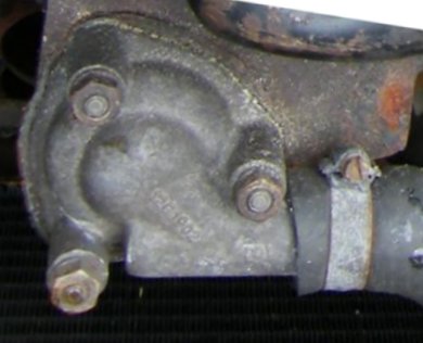
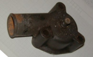
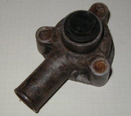
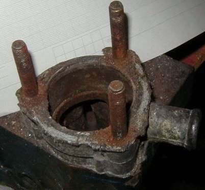
THERMOSTAT HOUSINGS
FILE (OR SAW) A 1mm STEP IN THE MATING FACE OF THE HOUSING ON THE OUTSIDE OF EACH BOLT HOLE, THIS ALLOWS YOU TO LEVER IT OFF WITH OUT DAMAGING THE SEALING FACE IF IT'S STUCK(CORRODED) ON.
DRILL HOLES OUT ONE SIZE UP AND GREASE THE STUDS ON ASSEMBLY, THIS SHOULD STOP THE STUDS WELDING THEMSELVES TO THE HOUSING EVER AGAIN.
IN THEORY HOUSINGS WILL ONLY FIT ONE WAY BECAUSE THE PITCH OF THE HOLES IS DIFFERENT BUT THE LARGEST TO SMALLEST PITCH IS ONLY 2mm DIFFERENT SO IF YOU SLOT THEM SLIGHTY OR EVEN JUST OPEN THEM UP A COUPLE OF MILLIMETERS AND THEY WILL POINT ANYWAY YOU WANT.
OTHER HOUSINGS - THIS IS
PHOTOS AND DIM'NS OF VARIOUS THERMOSTAT HOUSINGS USED ON A SERIES (SPRITES
MINIS A40S MAESTRO MONTEGOS ETC.
WATER PUMPS
S_MRW3709 IS A STANDARD SOLID IMPELLER
Q_QCP3709P IS A HIGH CAPACITY FABRICATED IMPELLER
Remember whichever pump you use, if you're using
a lot of revs the pump can rotate too quickly and cause over heating through
cavitation. To overcome this you need to fit a bigger diameter pulley to
the water pump which will slow it down.
BY PASSING THE HEATER
DURING THE SUMMER OR IF YOUR RACING YOU DON'T WANT A HEATER.
RACERS USUALLY REMOVE IT TOTALLY AND REPLACE IT WITH A PIPE AND BLANKING
PLATE OVER THE AIR INTAKE.SEE DIA
I'VE SHOWN AN EARLY VERTICAL RAD HERE BUT THE PRINCIPAL IS THE
SAME FOR THE CROSS FLOW RAD. 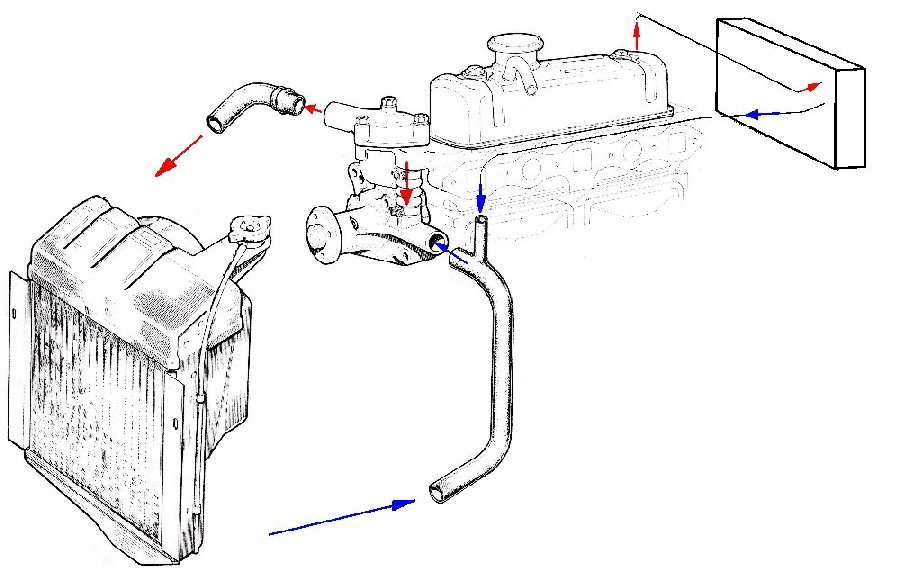
THE THEORY OF THE COOLING SYSTEM. AS YOU CAN SEE HOT WATER FROM THE
ENGINE COMES OUT THE BY-PASS HOSE INTO THE PUMP AND ALSO THRO' THE BACK
OF THE HEAD AND INTO THE HEATER AND IS COOLED AND PUMPED BACK INTO
THE ENGINE. THIS CYCLE CONTINUES UNTIL THE ENGINE WARMS ENOUGH TO OPEN
THE THERMOSTAT WHEN HOT WATER CAN ALSO GO TO THE RAD GET COOLED AND
THEN IS PUMPED BACK IN TO THE ENGINE.
AS STANDARD YOU COULD TURN A TAP AT THE BACK OF THE HEAD THAT STOPS THE FLOW OF WATER FROM THE HEAD TO HEATER, BUT THIS CHANGES THE WATER FLOW INTERNALLY AND CAN CAUSE HOT SPOTS AROUND No 4 CYLINDER AND SO DURING THE SUMMER ALOT OF OWNERS PUT IN A PIPE FROM THE BACK OF THE HEAD THAT MISSES OUT THE HEATER. THIS IS OK BUT IT CAN CAUSE A MORE GENERAL OVER HEATING PROBLEM DURING VERY HOT WEATHER AS IT IS TAKING HOT WATER AND PUTTING IT STRAIGHT BACK INTO THE ENGINE.
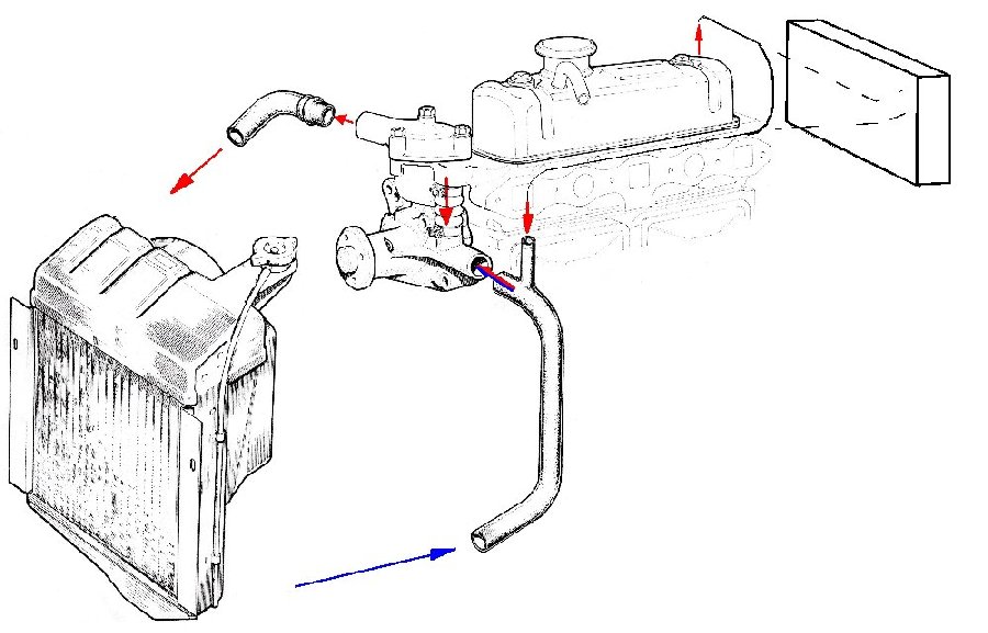
AS YOU CAN SEE THIS TIME HOT WATER IS COMING FROM THE BACK OF THE HEAD
AND MIXING WITH THE COOL WATER AND GOING STRAIGHT BACK INTO THE ENGINE.
A BETTER SOLUTION IS EITHER TO GET A NEW PIPE WITHOUT
THE HEATER CONECTION OR TO BLANK THE PIPE THAT TAKES IT BACK INTO THE ENGINE
(WATER PUMP HOSE TO RADIATOR BOTTOM) AND PUT A TEE PIECE IN THE TOP HOSE
(THERMOSTAT TO RADIATOR TOP). THIS MEANS THE HOT WATER COMES OUT OF THE
BACK OF THE HEAD AND THEN GOES INTO THE RAD. ALSO THE HEATER BOX-FAN UNIT
CAN BE REMOVED AND A PLATE FITTED OVER THE CROSSMEMBER HOLES TO SEAL IT. 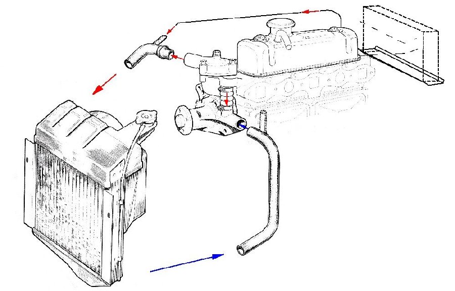
ANOTHER TRICK I USED ON ONE CAR WAS TOO FIT AN OIL COOLER IN THE HEATER
BOX, THUS YOU COULD CONTROL THE AIRFLOW THRO' IT AND THUS THE OIL TEMP
WITH THE FAN AND FLAP CONTROLS. ONLY ONE DRAW BACK IT MADE THE CAR VERY
HOT IN THE SUMMER